Synth connoisseurs with a geek mentality have been circuit bending electronic instruments and creating custom modifications for some time, but it’s highly unusual for a large manufacturer to offer a synth in kit form.
Yet that’s exactly what Korg has done with the launch of a kit form of its iconic monophonic analog synth, the MS-20.
Korg says that “creating an instrument your own hands is the part of the true enjoyment of an analog synthesizer. The MS-20 Kit lets you obtain a real, full-sized MS-20 by assembling it yourself.”
As with the MS-20 mini launched last year, Korg’s original MS-20 engineers have overseen this project. The MS-20 kit arrives 36 years after the original instrument’s launch in 1978.
The original MS-20 used different VCF circuits depending on the date of production. Units produced in the earlier period used a filter noted for its distinctive distortion and self-oscillation, while the filter used in later units was a low-noise design with a more mellow character.
Amazingly, this new MS-20 Kit provides both filters. You can switch between the two by moving a jumper pin on the circuit board according to your taste or needs.
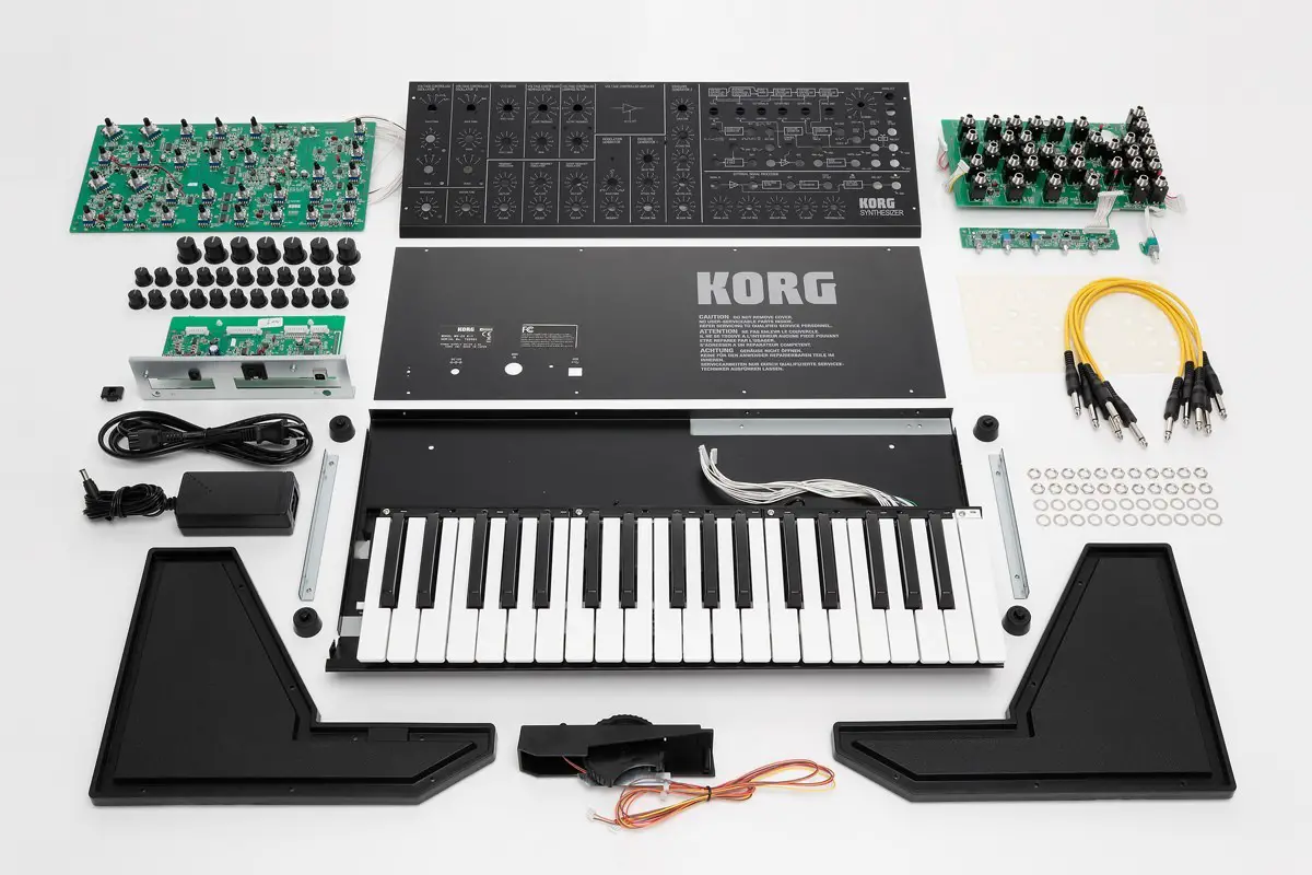
Package contents of the MS-20 Kit
Front panel, Rear panel, Bottom panel, L-shaped bracket(x 2), Left side pane, Right side panel, Left side shield, Right side shield, Panel support, Knob (large) (x 7), Knob (small) (x 29), Rubber bushing (x 10), Rubber feet (x 4), Cord hook, Nut 12 mm – shiny (x 36), Washer (x 36), Screw (x 36), Nut 11 mm – matte (x 30), Nut 11 mm – shiny (x 6), Keyboard unit, Wheel unit, Rear jack circuit board unit, Left panel circuit board, Right panel circuit board & VR circuit board (small), VR circuit board (large), Power supply circuit board, Box-end wrench (included)
Specifications in details
Control Section
1. Keyboard
: C ? C 37Keys(3 octaves)
2. Voltage Controlled Oscillator 1 (VCO 1)
: Scale (32′, 16′, 8′, 4′) (6 octaves, +cent, -cent)
: Wave form(Triangle, Sawtooth, PW-Square, White Noise) (4 modes)
: Pulse width adjust 1:1 ? 1:infinity
3. Voltage Controlled Oscillator 2 (VCO 2)
: Scale (16′, 8′, 4′, 2′) (6 octaves, +cent, -cent)
: Wave form(Sawtooth, Square, Pulse, Ring modulator) (4 modes)
: Pitch( ± 1 octave)
4. VCO Master control : Master tune( ± 100cent)
: Portamento(max. 10sec)
: Frequency modulation intensity by MG/T.EXT(-5V ? +5V)
: Frequency modulation intensity by EG1/EXT(-5V ? 0V)
5. VCO Mixer
: VCO 1 Level
: VCO 2 Level
6. Voltage Controlled High Pass Filter (VCF HPF)
: Cutoff frequency(50Hz ? 15,000Hz)
: Peak(flat ? self OSC)
: Cutoff frequency modulation intensity by MG/T.EXT(-5V ? +5V)
: Cutoff frequency modulation intensity by EG2/EXT(-5V ? +5V)
7. Voltage Controlled Low Pass Filter (VCF LPF)
: Cutoff frequency(50Hz ? 15,000Hz)
: Peak(flat ? self OSC)
: Cutoff frequency modulation intensity by MG/T.EXT(-5V ? +5V)
: Cutoff frequency modulation intensity by EG2/EXT(-5V ? +5V)
8. Envelope Generator 1
: Delay time(10sec)
: Attack time(10sec)
: Release time(10sec)
9. Envelope Generator 2
: Hold time(20sec)
: Attack time(10sec)
: Decay time(10sec)
: Sustain level(0V ? 5V)
: Release time(10sec)
10. Modulation Generator (LFO)
: Wave form(Negative Sawtooth ? Triangle ? Positive Sawtooth, Wide Pulse ? Square ? Narrow Pulse)
: Frequency(0.1Hz ? 20Hz)
11. Manual controller
: Cntrol wheel(center click)
: Momentary switch –>GND
12. Power switch and Volume
: Volume
13. Indicator
: LED(KBD trigger, Modulation Generator rate, Power ON)
External Signal Processor
1. Control section
: Input signal level
: Low cut frequency(50Hz ? 2,500Hz)
: High cut frequency(100Hz ? 5,000Hz)
: CV adjust
: Threshold level
2. Input and Output
: Signal In
: Amplifier Out
: Band pass filter Out
: CV Out(0 ? +8.4V)
: ENV Out(0 ? +5V)
: Trig Out(+5V–>GND)
3. Indicator(LED)
: Peak indicator
: Trigger indicator
Patch Panel
1. Keyboard
: Keyboard control voltage output(Exponential) (0 – +8V)
: Keyboard trigger output(+5V–>GND)
: VCO-1 + VCO-2 control voltage input(Linear response)(0 – +8V)
: VCO-2 control voltage input(Linear response) (0 – +8V)
2. VCO
: VCO-1 + VCO-2 external frequency control input(OCT/V)(-5V – +5V)
3. VCF
: External signal input(3Vp-p max.)
: External High pass filter cutoff frequency control input(2OCT/V)(-5V – +5V)
: External Low pass filter cutoff frequency control input(2OCT/V)(-5V – +5V)
4. VCO + VCF
: Total external modulation input(T.EXT)(-5V – +5V)
5. VCA
: External initial gain control input(0 – +5V)
6. EG
: EG 1 envelope signal normal output(0V – +5V)
: EG 1 envelope signal reverse output(+5V – 0V)
: EG 1 + EG 2 trigger input(–>GND)
: EG 1 trigger input(–>GND)
: EG 2 envelope signal reverse output(+5V – 0V)
7. MG
: Triangle output(Negative Sawtooth – Triangle – Positive Sawtooth)(5Vp-p)
: Rectangle output(Wide Pulse – Square – Narrow Pulse)(0 – +5V)
8. Noise Generator
: Pink noise output(5Vp-p)
: White noise output(5Vp-p)
9. Sample and Hold
: Clock trigger input(–>GND)
: Sample signal input(5Vp-p max.)
: S/H output(5Vp-p max.)
10. Modulation VCA
: Control voltage input(0 – +5V)
: Signal input(-5V – +5V)
: Signal output(-5V – +5V)
11. Manual controller
: Control wheel output(-5V< --0V-->+5V)
: Momentary switch output(–>GND)
12. Signal out
: Signal output(2Vp-p output impedance 3.5k ? )
13. Head phones
: Head phones output(33 ? 48mW)
14. USB
: Type B, USB-MIDI Input/Output
*Only note messages (velocity is not used) can be transmitted and received.
15. MIDI
: MIDI Input
*Only note messages (velocity is not used) can be transmitted and received.
Exact availability and pricing to be confirmed.